


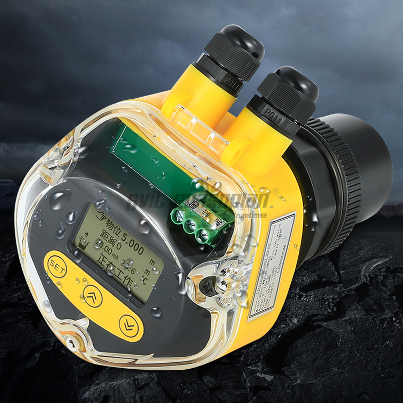
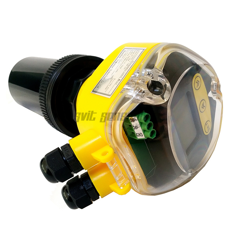
Ultrasonic level gauges are digital level gauges controlled by a microprocessor. In the measurement, the ultrasonic pulse is sent by the sensor (transducer), the sound wave is reflected by the liquid surface and then received by the same sensor, converted into an electrical signal by the piezoelectric crystal, and the time between the transmission and reception of the sound wave is calculated from the sensor to the received signal. Measure the distance to the surface of the liquid. Due to the non-contact measurement, the measured medium is almost unlimited, and it can be widely used for the height measurement of various liquid and solid materials.


Basic Parameters
|
Function |
Integrated Type |
Separate Type |
|
Measuring range |
5m, 10m, 15m, 20m, 30m, 40m, 50m, 60m |
5m, 10m, 15m, 20m, 30m, 40m, 50m, 60m, 70m |
|
Measurement accuracy |
0.5%-1.0% |
0.5%-1.0% |
|
Resolution ratio |
3mm or 0.1% (whichever is greater) |
3mm or 0.1% (whichever is greater) |
|
Display |
English LCD |
English LCD |
|
Analog output |
4-line system, 4~20mA/ 510Ω load 2-line system, 4~20mA/ 250Ω load |
4~20mA/ 510Ω load |
|
Relay output |
2 groups (i.e. AC 250V/ 8A or DC 30V/ 5A) optional, state programmable |
2 groups for single channel and 4 groups for double channels (optional) AC 250V/ 8A or DC 30V/ 5A, state programmable |
|
Power supply |
Standard configuration: 24VDC Optional: 220V AC+15% 50Hz |
Standard configuration: 220V AC+15% 50Hz Optional: 24VDC 120mA Customized: 12VDC or battery powered |
|
Ambient temperature |
Display instrument: -20~+60ºC Probe: -20~+80ºC |
Display instrument: -20~+60ºC Probe: -20~+80ºC |
|
Communication |
485, 232 communication (optional) (manufacturer agreement) |
485, 232 communication (optional) (manufacturer agreement) |
|
IP grade |
Display instrument: IP65, probe: IP68 |
Display instrument: IP65, probe: IP68 |
|
Probe cable |
None |
100m available, standard configuration: 10m |
|
Probe installation |
Select type based on measuring range and probe |
Select type based on measuring range and probe |
Power Consumption
|
Product power consumption |
The power supply of separate type is 24V power and the electricity consumed for such type is 100mA without relay, 120mA with a replay, 145mA with 2 relays, 170mA with 3 relays and 190mA with 4 relays. Specific power consumed is shown in below: 24×100mA=2.4W for separate type without relay; 24×120mA=2.9W for separate type with a relay; 24×145mA=3.5W for separate type with 2 relays; 24×170mA=4.1W for separate type with 3 relays; 24×190mA=4.6W for separate type with 4 relays; |
|
Product power consumption |
The integrated type with four-wire system is powered by 24V power supply and its electricity consumed is 80mA without relay, 105mA with a relay and 130mA with 2 relays. Specific power consumed is shown in below: 24×80mA=1.9W for integrated type without relay; 24×105mA=2.5W for integrated type with a relay; 24×145mA=3.1W for integrated type with 2 relays; |
|
Product power consumption |
The integrated type with two-wire system is powered by 24V power supply. It cannot be equipped with relay and its electricity consumed is 30mA. Specific power consumed is shown in below: 24×30mA=0.72W for integrated type without relay; |
Remarks: this series of ultrasonic probe can also be customized as per client's demand and the customized probes are probes with special specification requirements, such as resistance to high pressure, resistance to high temperature, small diameter and small blind area.
Why you should purchase from us?:


Wiring Diagram:
★ Prompt: make sure the connecting cable between the probe and meter body of separate-type ultrasonic level meter is long enough in advance. Connection with other cable for extension on site is not allowed as it will affect the signal transmission quality and strength.
★ During power line connection, AC power line shall not be connected to any other terminals except AC terminals. Otherwise, the meter circuit or components and parts will be burnt.
★ 485, 232 and 4-20ma output terminals shall not be short-circuited as short circuit will lead to burning of internal circuits.
The cables connecting the sensor and main equipment shall not be put in a trunking with any alternating current. If it can not be prevented, the cables of sensor shall be protected by a cable conduit to completely shield the electromagnetic interference caused by alternating current.
(1) Electric wiring diagram of standard single-probe separate-type ultrasonic level meter:


Wiring method:
Grounding: first make sure the grounding terminal of the meter is actually grounded and the meter does not share ground terminal with other equipment and then connect terminal 4.
Transducer: red wire: connected to Trans1 (transducer);
blue wire: Temp 1 + temperature sensor +
Black wire: GND (ground wire)
Current output: “current +” connected to mA1 +;
“current -” connected to mA- /GND
Relay: RLlnA and RLnB are normally open;
To ensure the default state of relay is “normally open”, RLlnA and RLnB shall be connected.
RlnA and RLnC are normal closed.
To ensure the default state of relay is “normally closed”, RLlnA and RLnC shall be connected.
Power line: AC: connected to L and N
DC: 24V+ connected to 24VDC+ and 24V- connected to 24V DC-.
(2) Wiring diagram of integrated-type:
◆ Enhanced integrated type with four-wire system
Electric Wiring Diagram of Enhanced Integrated Type with Four-wire System:

24VDC Power Supply Wiring Diagram of Four-wire System:

220VAC Power Supply Wiring Diagram of Four-wire System

◆ Enhanced integrated type with two-wire system
Electric Wiring Diagram of Two-wire System

Wiring Diagram of Two-wire System + Ampere Meter Diagram of Two-wire System:

◆ Explosion-proof integrated type with four-wire system
Electric Wiring Diagram of Explosion-proof Integrated Type with Four-wire System

24VDC Power Supply Wiring Diagram of Four-wire System

220VAC Power Supply Wiring Diagram of Four-Wire System:

◆ Explosion-proof integrated type with two-wire system
24VDC Electric Wiring Diagram of Explosion-proof Integrated Type with Two-wire System

Wiring Diagram of Explosion-proof Integrated Type with Two-wire System + Connection of Explosion-proof Integrated Type with Two-wire System and Ampere Meter:

It is important for the users to understand the below terminologys before the installation operation:
1: Measuring range: the meaning of measuring range is very important for meter type selection. Please refer to the diagrams below:

2: Emitting angle and false echo:
Ultrasonic wave beam is gathered by the probe. The emitting of impulse wave beam is like the light beam of flashlight. The further it is from the probe, the greater the diffusion area is.
Any objects within the range of emitting angle, such as pipe, support, weld joint, reinforcing rib, mixing propeller and hanging object, will lead to strong false echo, specially the objects within the range of emitting angle which are near the probe.
For example, the false echo caused by the pipe at 6m from the probe is 9 times stronger than that caused by the same pipe at 18m from the probe.
★Try every effort to make the sensor axis perpendicular to the medium surface and avoid any other object within the range of emitting angle, such as pipe and support.
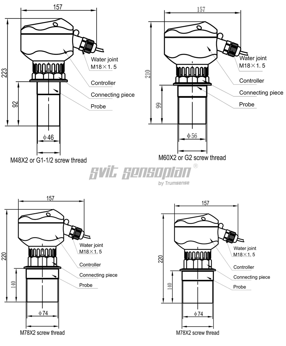
Sizes of Integrated Ultrasonic Liquid Level/ Power Height Sensor:
Typical Wrong Installation (only examples):

Screw Installation of Integrated Ultrasonic Water/Material Level Meter:

Bracket Installation of Integrated Ultrasonic Water/Material Level Meter:

Installation of thread at the bottom:
It is recommended to use plastic flange to connect with the sensor during the installation:

★After probe installation, the probe emission surface must be exposed from the cover plate or waveguide and it shall not be in the cover plate or waveguide.
Open container Installation:
For open container, the support shall be used for installation. The bearing capacity of support shall be noted and certain distance shall be kept between the sensor and container wall. If the upper part and lower part of the open container or stock bin inner wall are flat and free of hanging objects and any other objects, the distance between the sensor and container wall is detailed as follows:

Installation on open container – with top against the support at one side
As the open container has no focusing effect, the sensor can be installed in the middle of the container.

Draining well and common well Installation:
Normally, the wellhole and wellhead of drainage well are narrow and the well wall is uneven, which makes it difficult to conduct ultrasonic measurement. This can be solved by installing a section of connecting pipe or a whole measuring casing. Attention shall be paid to the fact that the blind area will be enlarged for about 50~100% after the sensor is put into the connecting pipe. So the factors for blind area expansion shall be considered.
Thus, when the connecting pipe is used, if the original probe blind area is 0.50m, it will be enlarged to 1.00m after the probe is put into the connecting pipe.
 For common well (including water source well and deep well), normally the diameter is small and the best measuring effect can be reached by installing measuring casing. The inner wall of measuring casing must be smooth (PVC and PE pipe can be used) and the inside diameter shall be ≥150mm (measuring range within 4m). The manufacturer shall be contacted for connecting pipe longer than 4m. The measurement can be carried out as long as the measuring casing is clean and free of attached medium and internal joint.
The measuring casing shall be soaked in the medium all the time, which can ensure the accurate measurement within the measuring casing.
Flange installation of Solid Measurement:
Similar to liquid medium measurement, the meter can be installed on the counter flange of container connecting pipe. The solid reflecting surface is different from that of the liquid and it is not a plane, which shall be considered during installation. The probe emitting surface shall be perpendicular to the surface of solid to be measured and the probe shall be exposed from the connecting pipe.
At the solid measurement site, in most cases, probe inside the connecting pipe will lead to pulsating of measured data or “wave loss”.
To solve the problem, the universal flange can be used. In this case, the probe emitting surface can easily be aligned to the reflecting surface of the solid to be measured merely by rotating the flange.
Integrated-type sensor installed on container flange:

Separate-type sensor installed on container flange:

Installation via nipple joint for solid measurement:
During installation via nipple joint, the probe must be exposed for at least 2cm above the connecting pipe bottom.

Doorframe installation for solid measurement:
Doorframe installation can be applied for the open container and the axis of connecting pipe must be aligned to the container opening or perpendicular to the medium surface.

During installation for material piles in the open air, several meters are required for the measurement of large material pile in the open air. The meters can be fixed on the hoist frame and sensor probe shall be aligned to the medium surface.


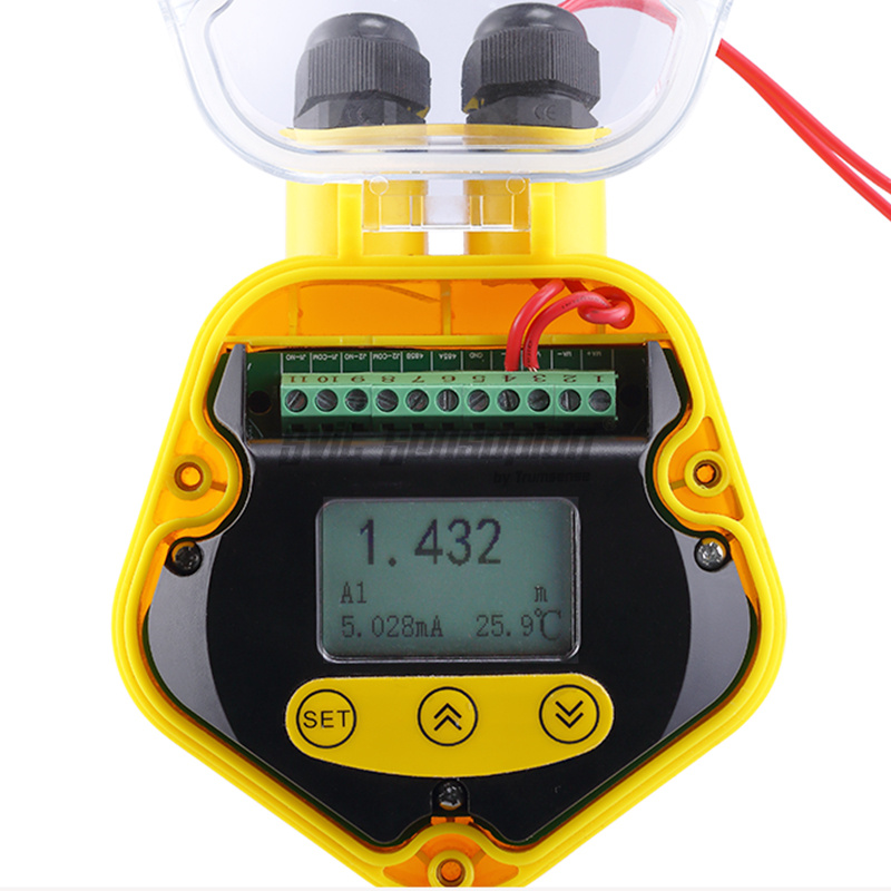
If all wirings are normal through inspection in case of a fault, after ultrasonic level meter is grounded, you can keep pressing "▲", then press "SET" to show echo menu, take a photo of the echo menu and send it to us via MMS or picture. By this way, we can determine the possible electromagnetic interference, false echo, situation of entering a blind area, no echo signal received and other faults.
|
Faults |
Causes |
Handling |
|
Level meter does not work. |
Power supply is not well connected. |
Inspect power line. |
|
Level meter does not display data. |
1.Power supply is not well connected. 2.Wiring between LCD and mainboard falls off or comes loose. 3.The LCD is damaged. |
1.Inspect power line.
2.Inspect the wiring and connect it again.
3.Maintain it in the factory. |
|
Level meter works but there is no change of trumpet icon (▲) on the LCD, which means that the system is in wave loss state. |
1.The measured area is beyond the measuring range of level meter.
2.The measured medium has strong disturbance, vibration or heavy dust.
3.There are strong interference sources around such as frequency converter and motor.
4.The probe is not aligned to the measured surface.
5.There are redundant objects in the measured space, such as support rod and feed opening.
6.The liquid level is in a blind area.
7.The measured medium is soft powder or there is foam on liquid surface. |
1.Replace the level meter with a level meter with greater measuring range.
2.The meter will restore the normal measurement automatically after the measured medium gets back to calm.
3.Check surrounding environment and realize good electromagnetic shielding. Do not share one power supply with frequency converter and motor, and make it grounded reliably.
4.Reinstall probe and make it perpendicular to liquid surface.
5.Select an appropriate position for installation and prevent an interfering object.
6.Raise the installation position of probe.
7.Check whether the medium is powder. If so, consult the manufacturer. |


Liquid level and material level measurement is a common problem in industry. Ultrasonic position measurement technology has many advantages. It can not only measure position at fixed point and continuously, but also provide signals needed for telemetry or remote control. Compared with radioactive positioning technology, ultrasonic technology does not need protection. Compared with laser ranging technology, it has the advantages of simple and economic. At the same time, ultrasonic technology generally does not require moving parts, so it is relatively convenient in installation and maintenance. Ultrasonic level meter can be widely used in petroleum, mining, power plant, chemical plant, water treatment plant, sewage treatment station, agricultural water, environmental protection monitoring, food ( brewing industry, beverage industry, additives, edible oil, dairy products ), flood control, hydrological monitoring, open channel, spatial positioning and many other industries.

This product has excellent chemical resistance. For inorganic compounds, regardless of acid, alkali or salt solution, except for strong oxidizing materials, almost all of them have no destructive effect on them. Almost all solvents are insoluble at room temperature. , hydrocarbons, alcohols, phenols, aldehydes, ketones and other media can be used.


